
WIND VANE PROJECT
by Jon Edison
If you visit any F3F contest you will be amazed at the amount of equipment that has to be provided to do the turn pylons, the race timing, and wind speed. But when it comes to the wind direction, this is left to the vagrancies of a wind sock or other form of ad hoc streamer. It is clear that an accurate means of measuring the wind direction was needed.
The FAI F3F rules state that a pilot is allowed a reflight if “ the direction of the wind constantly deviates more than 45deg from a line perpendicular to the main direction of the speed course.” Constantly meaning 20seconds or more Thus a means of measuring wind direction together with a timing element to for the 20 seconds is required. Following the success I had with my Timing Gear for the 2006 Viking Race, I set about the design of the Wind Vane using a PIC Microprocessor as the basis for this new project.
The PIC is a fantastic piece of kit. These devices can look a little intimidating on first appearances, but spend a little time looking through the many PIC Tutorials that exist on the web, and you will get a feel for these mighty little pieces of silicon. Working on the basis of keeping it simple, I ignore all the complex bits if I can, I set about putting together a list of routines needed for the project
The feedback pot in the servo is supplied with a 5v signal, from which the PIC measures the voltage returning from the pot wiper, giving in this case a 0 to 5v signal for a 180deg movement. So we are all set, a few hours later, and the design requirements have been sketched out.
The Wind Vane is to provide:-
A digital Readout of the wind direction
An Audible warning when the wind is off by 45deg or more
A Reset feature to silence the warning
A Serial output for a remote display
In addition, the unit must be useable as a stand alone device as well as being able to interface with my existing F3F Timer.The current design meets all those criteria. However as time has gone by, the digital display has become less of a requirement. The Vane itself provides the indicator for the wind direction, and coupled with some form of marker, will give a more than adequate indication of when the wind is approaching the limits. Plus the fact that the unit may be several meters up a pole, the digital readout is superfluous.
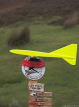
The Vanes first outing was at the 3rd Round of the Hole of Horcum Winter league. Here the Wind Vane, mounted with the electronics, waits patiently like the rest of us for the mist to clear. On the day this photograph was taken, the wind was square on to the slope and very smooth, so the Vane was somewhat superfluous!
Well so much for the electronics, what about the physical requirements? Well the Vane is straight forward, a pivoted stick with a large surface at one end, all mounted on some form of bearing. Engineering wise a bearing is not a major problem, but if there is something that is readily available and contains the means of housing the feedback mechanism for the electronics so much the better.
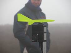
I have to admit it was not my idea, but a Hitec Servo turned out to be the ideal device. Here the prototype is taped unceremoniously to the peg board at the Hole of Horcum
( Mike Shellim photo )
Ideally, testing requires a wind of varying direction and to be somewhat turbulent. Those conditions giving a better idea of whether the correct amount of ‘damping’ has been applied. The ‘damping’ is in the form of an averaging routine, applied by the electronics to the signal coming in from the Vane. Thus if the vane was oscillating from side to side, with damping these oscillations are smoothed out allowing the point at which the wind is 45degree off to be detected. Without the damping it would be very difficult to know just when the wind was off, but too much would slow the response down, and introduce an unacceptable time delay to the signal.
Now I have working example, I can take to various events for ‘on the job’ testing.
More later.
Jon Edison