
 Case Details
 F3F TIMER PROJECT by Jon Edison
Updated March 2025
MK IV Construction Details
< Back ( Additional Components ) Next >
The new Timer departs from the original concept of a 'through hole' design and has moved on to a Surface Mount Design ( SMD ) . This is requires a revised construction technique, but is still within the scope of a competant modeller who has a modicum of electronics knowledge.
For those of you who would rather skip the construction bit, a fully assembled and tested PCB complete with USB interface, is available for £250. If it is required to have the PCB installed in a IP42 case, then this can be added for an additional £30
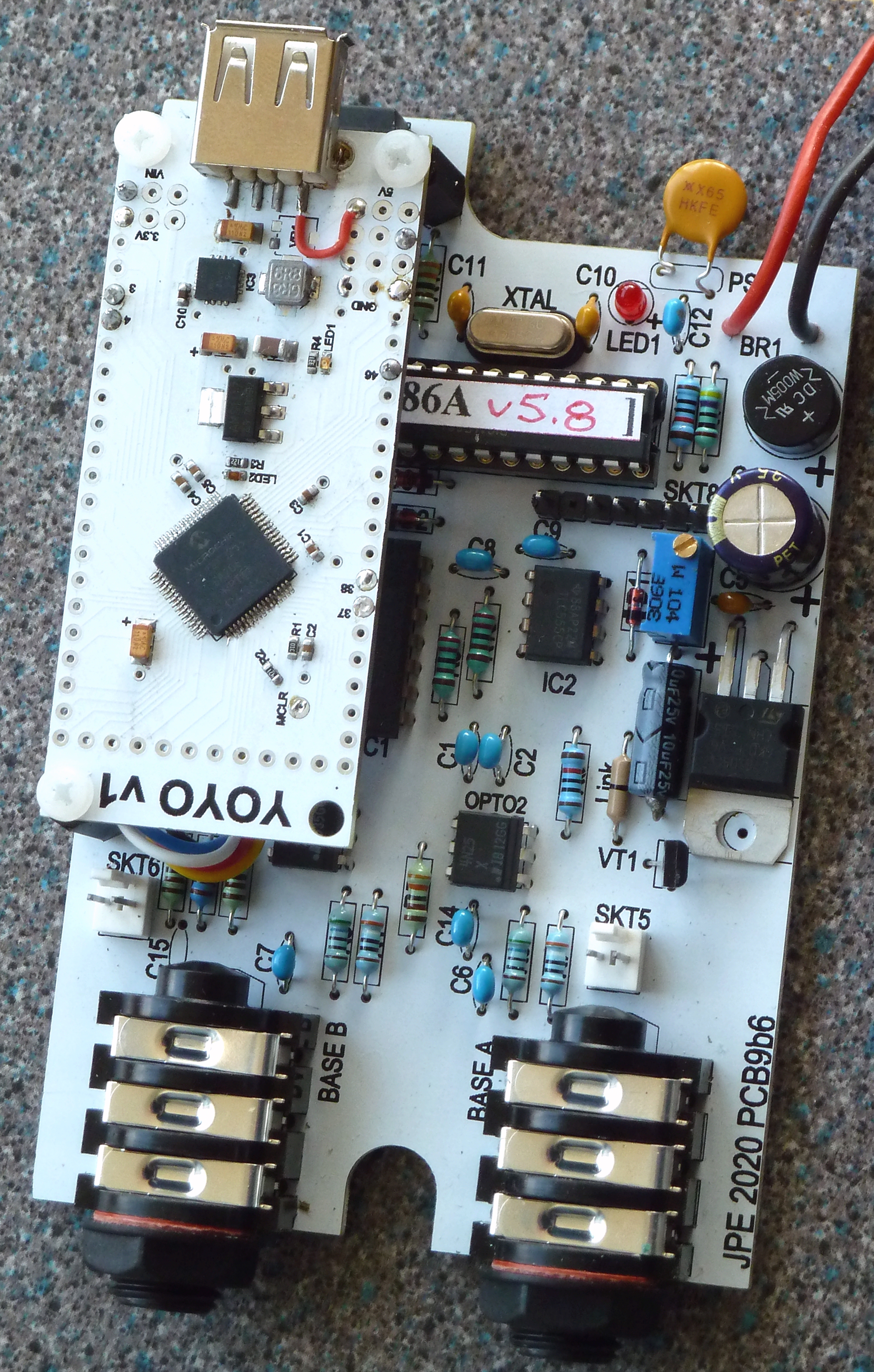
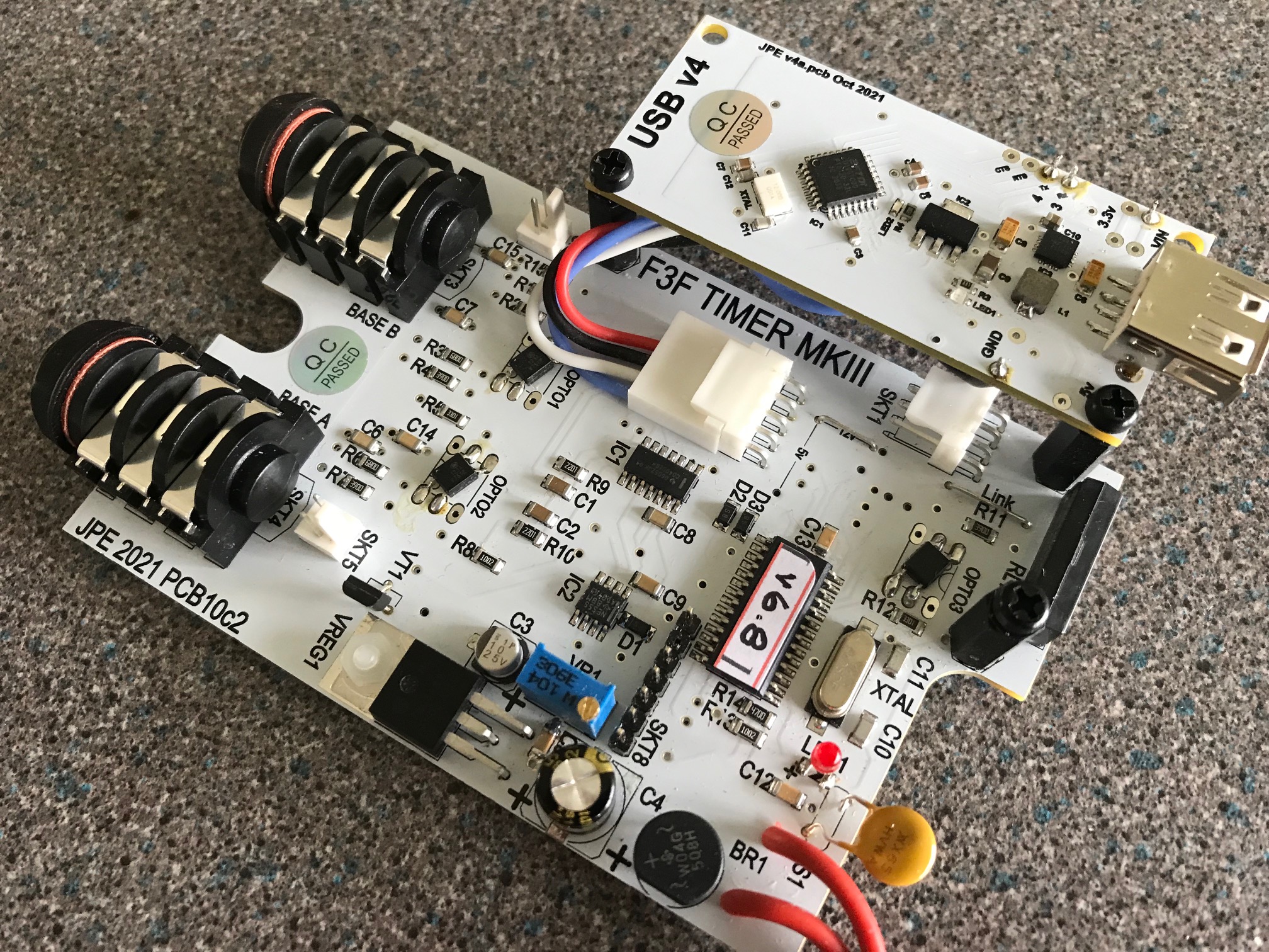
Mk IV PCB
This is available either directly from the Author, or can be manufactured by one on many PCB fabrication shops available. The Author uses PCBWAY , a chinese fab shop who produces quality boards at sensible prices and with a quick ( 1 week ) turnaround. All the gerber drawings and drill information are available here.
PCB Assembly
Construction of a SMD board requires a different technique to the 'through hole' process. The board drawings above, include a 'solder stencil'. This is a thin stainless sheet, with laser cut holes which correspond to the exact location of all the solder pads on the PCB.
The first process is to align the stencil and board, then with the stencil fixed in place, apply solder paste to the stencil and with a spatular, spread the solder into every hole in the stencil. Carefully check that no area is missed before removing the stencil.
Now using tweesers or suction device transfer all the SMD components carefully to the board and press each down into the small solder pads created in the last step. Once this is complete, the board is now heated to melt all the solder pads. The author uses a single ring hotplate controlled from a Android controller to heat the board up to the required temperature. c250degC
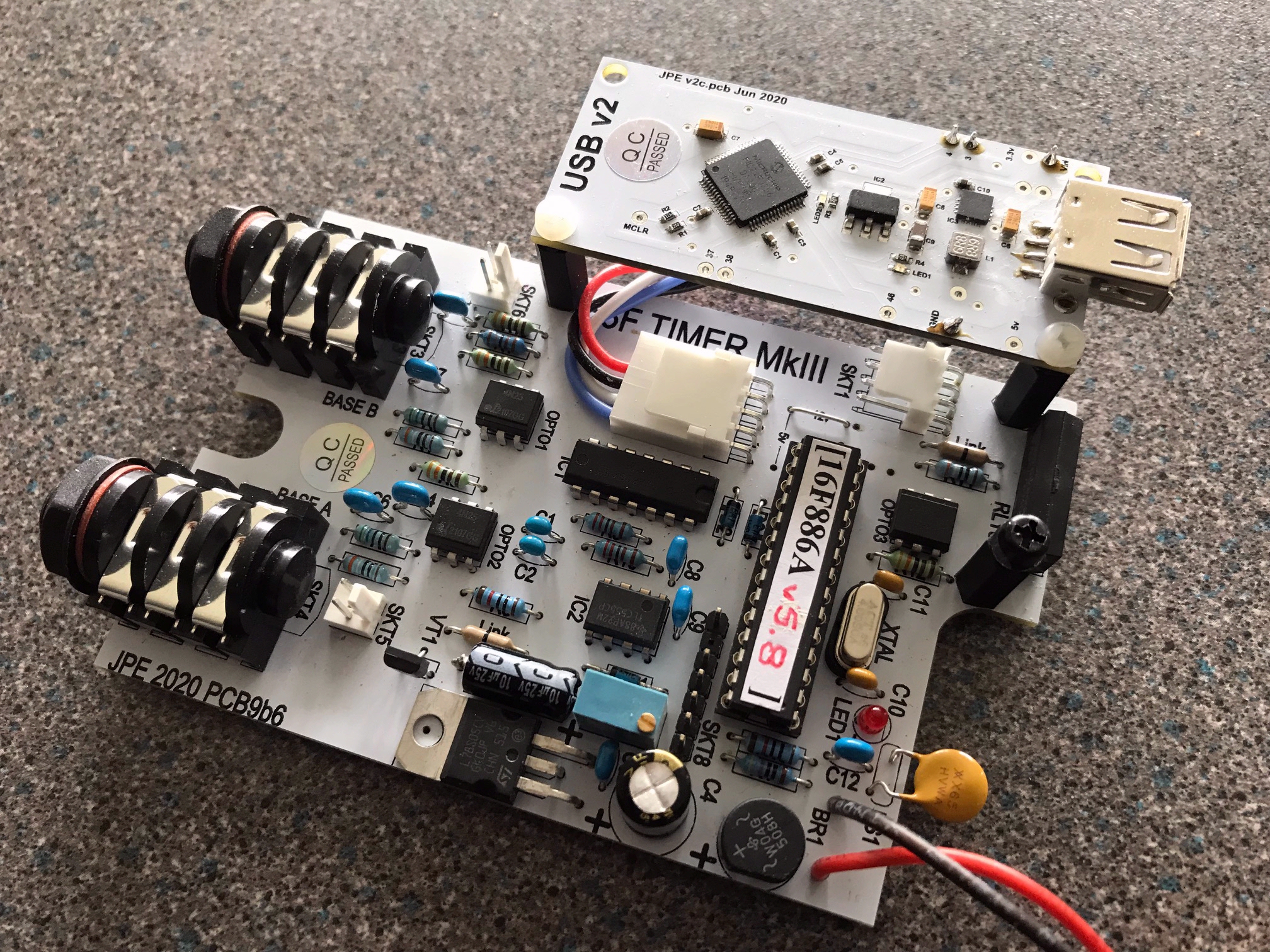
Once the solder flows, carefully remove the board and allow to cool down . Once cool, solder the few remaining through hole components and then test the board.
PSU's are usually the first items to check
PCB Testing
Case
New SMD PCB Components
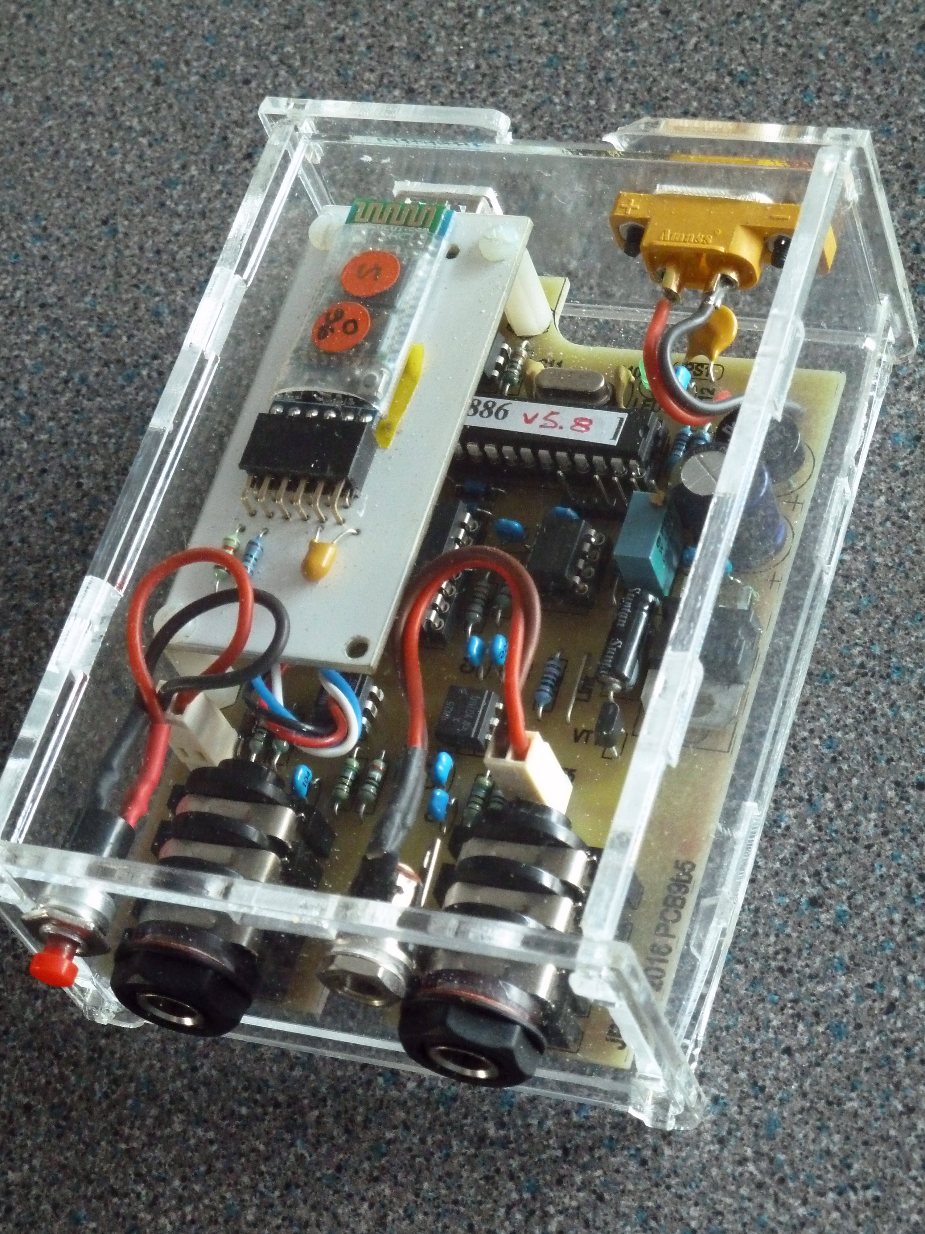
PCB in Show Case
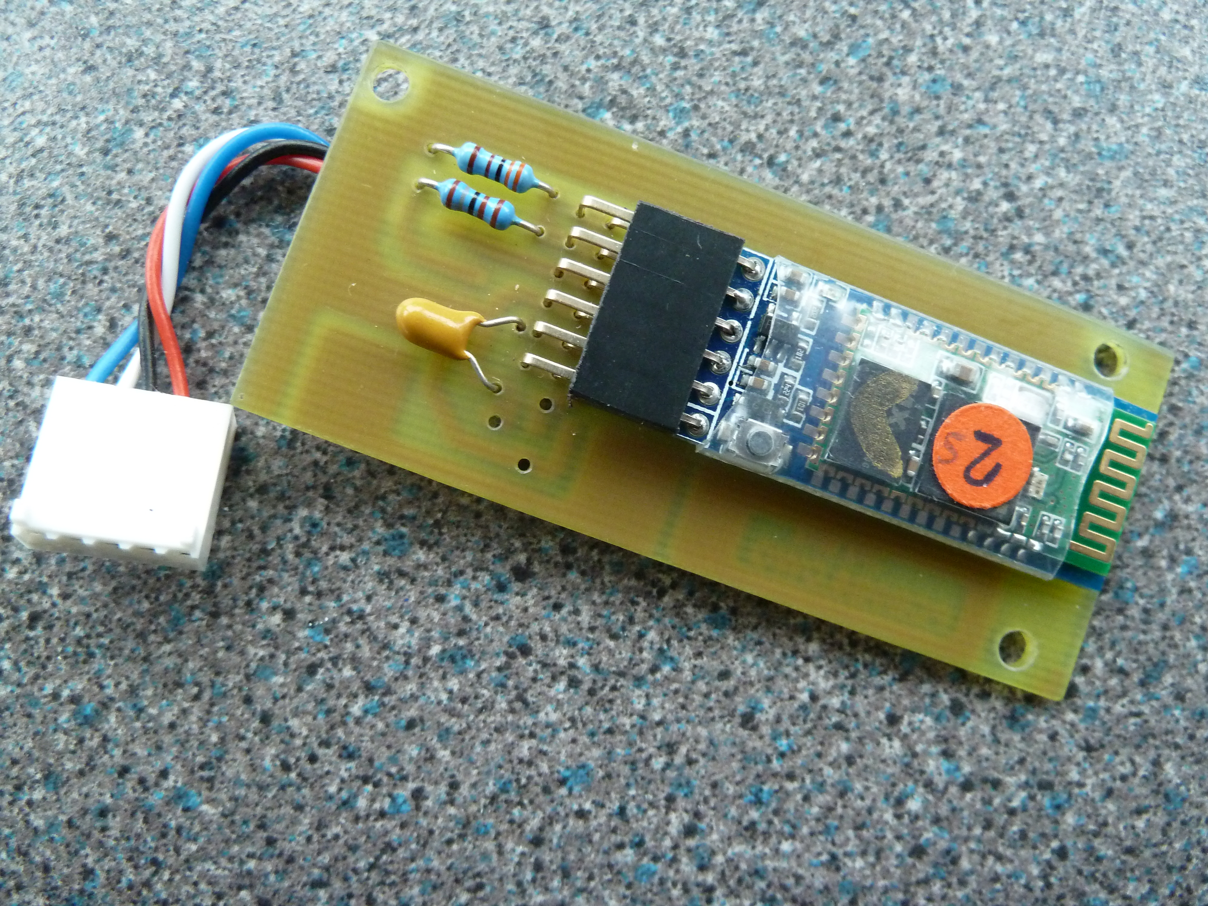 Bluetooth HC-05 Module
Jon Edison
March 2025.
New SMD PCB under Development
Disclaimer
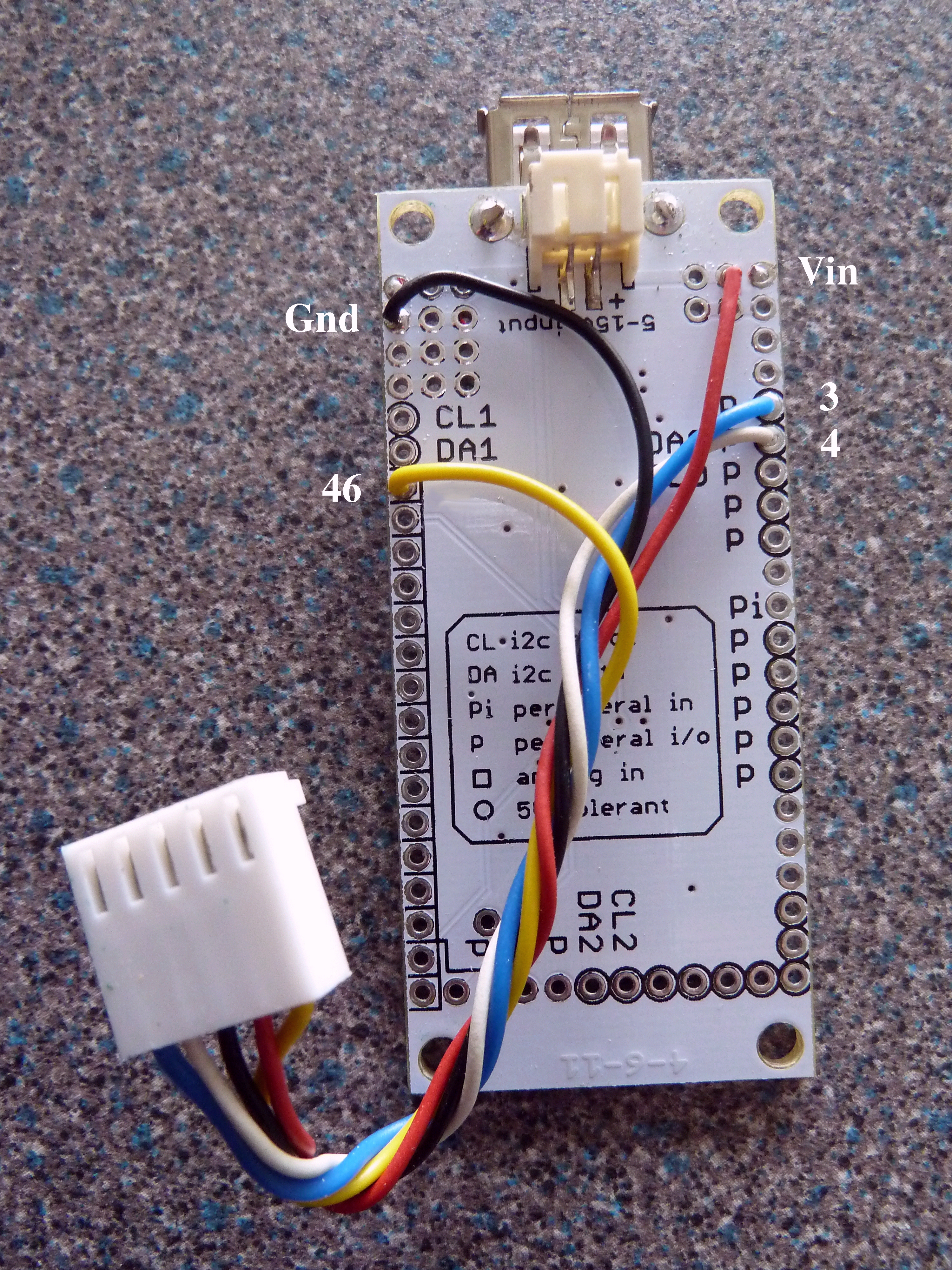 IOIO Connections
I have no connection with any of the companies listed, any links given are for information only, and for use at your own risk. All information is given in good faith and without liability.