
F3F TIMER PROJECT by Jon Edison
Created August 2020. Updated Nov 2020
Design and Construction of an Reflow Hotplate
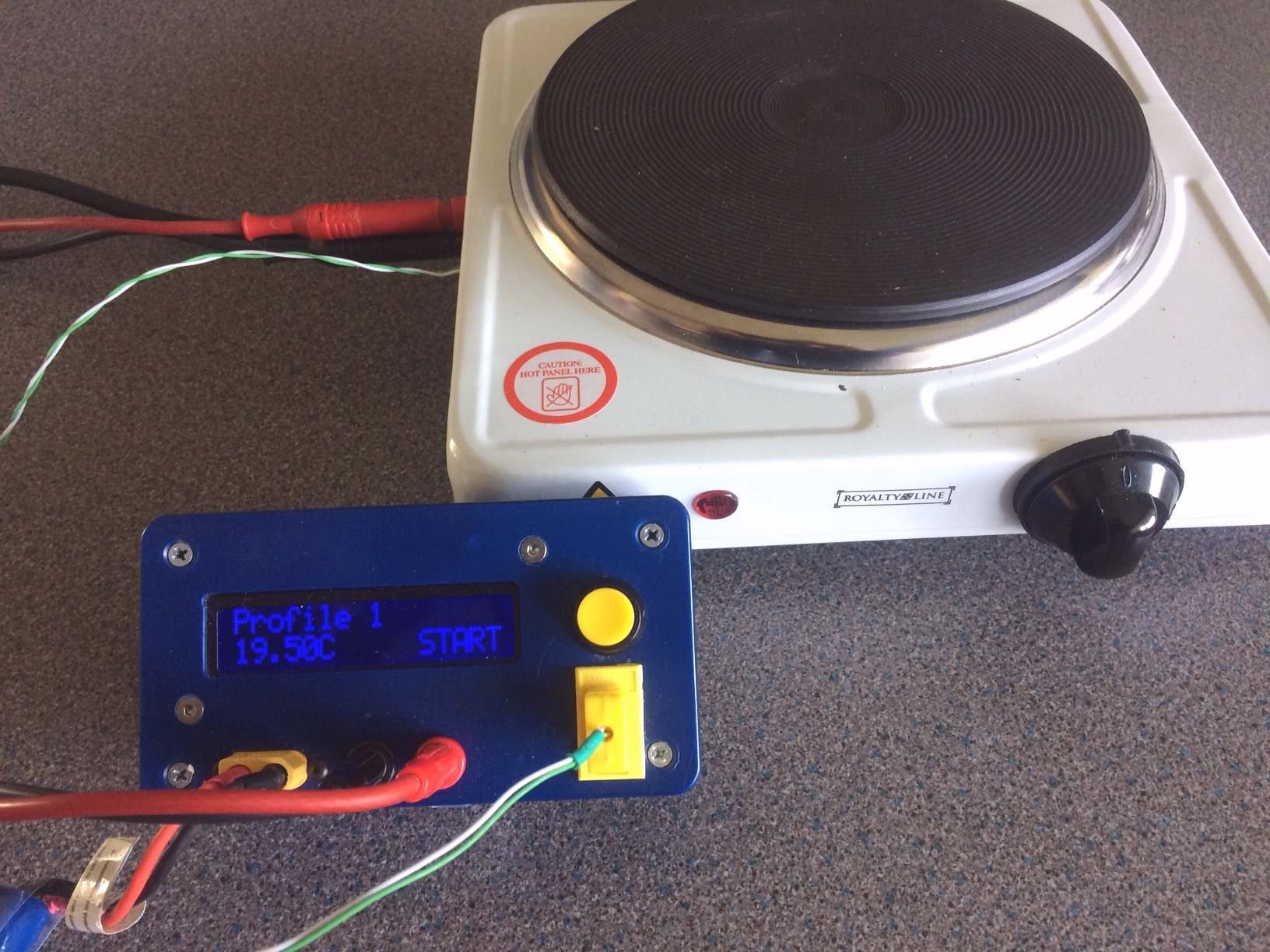
Hotplate and its Controller.
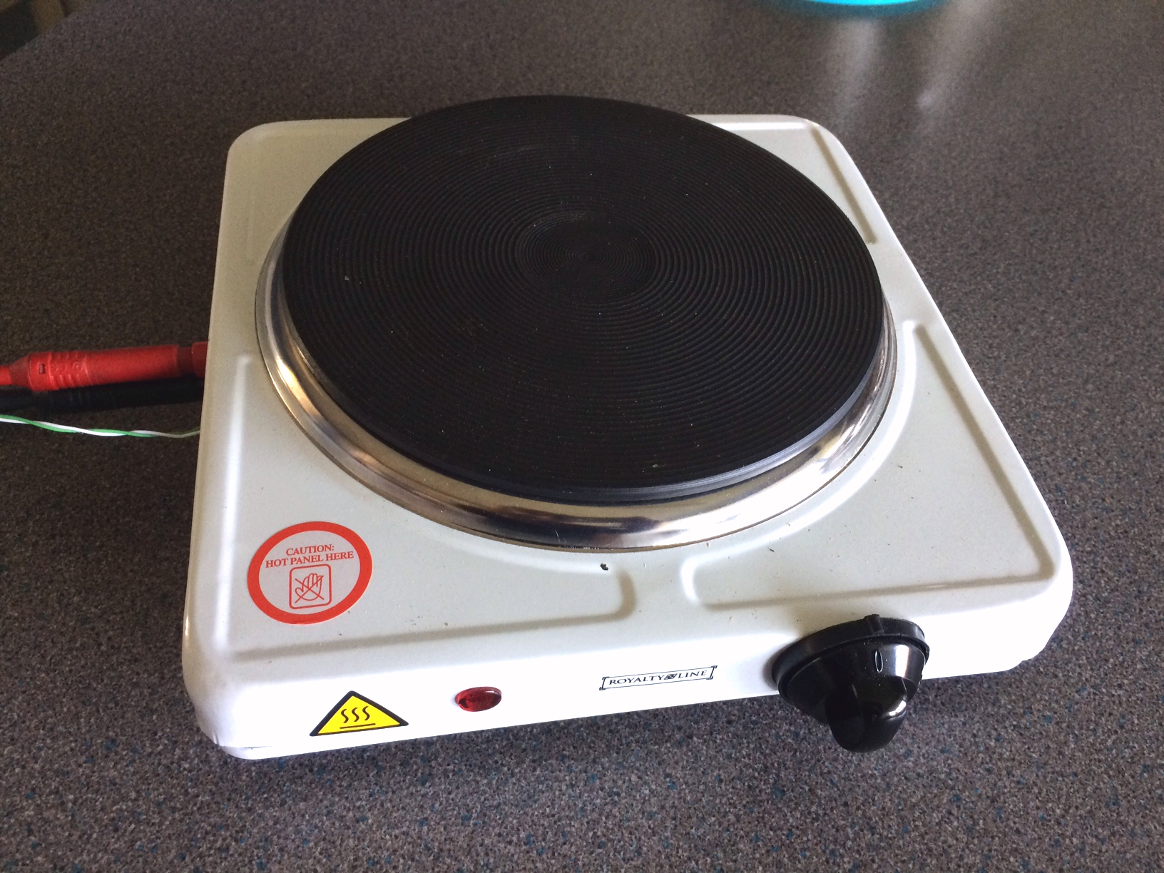
The Hot Plate consists of a standard single 1500W electric hob, modified with the addition of a Solid State Relay ( SSR ) and Thermocouple. This provides the temperature control and feedback from the hotplate to the Arduino based controller housed in a separate plastic box. For simplicity the Arduino controller is battery powered, thus separating the 'mains' high voltage section ie the hotplate, from the low voltage controller.
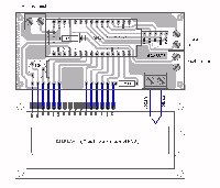
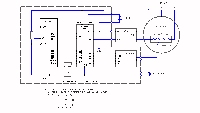
In order to minimise the number on connections between components, a PCB was designed to be used as shown.
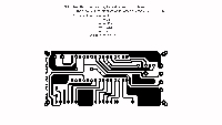
PCB
Produce the PCB using a photo etch process. Drill all holes 0.8mm. Open up holes for headers and connector Blocks to 1mm
PCB Assembly
Install the 1K and 220ohm resistors on the board first. Next solder Headers onto the board for both the Arduino Nano and the MAX6675. Mount the Arduino Nano, and MAX6675 on the headers. Note some versions of these components come with headers already in place, in which case use these where appropriate. Mount the 10K Trim Pot and then the three connector blocks for the Push Button, Battery and SSR.
Mount headers on the DISPLAY Panel to connect to the underside of the PCB. The PCB is the same size as the DISPLAY and the mounting holes are designed to align. Therefore, before finally soldering the PCB and DISPLAY together it may be helpful to hold the two components together with 3mm x 30mm long bolts and 5mm long spacers between them. These bolts will be useful for mounting the whole assembly into a suitable case later. A Hammond case type 1591, size 120 x 65 x 40mm was used on the prototype.
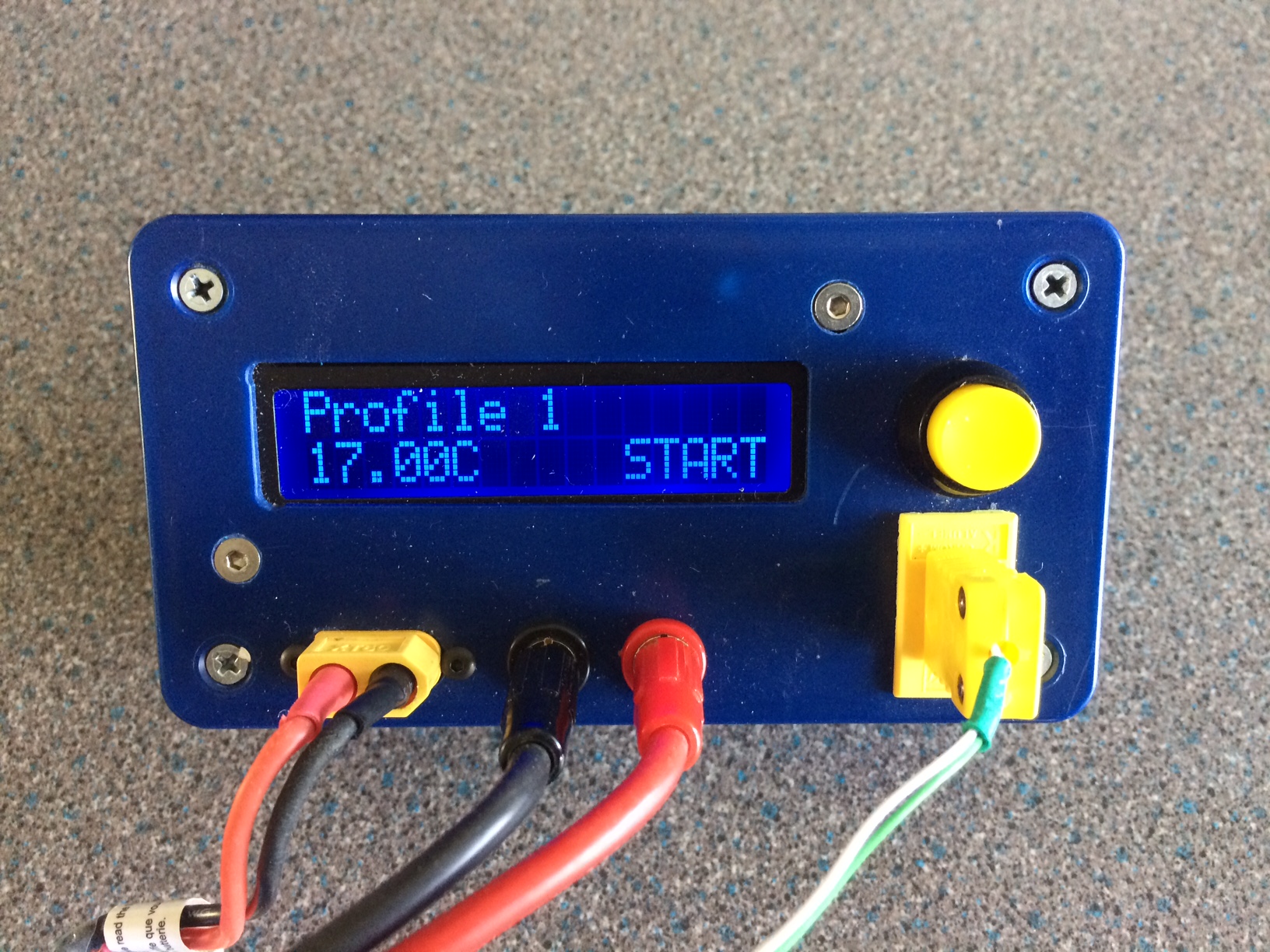
Progamme the Arduino using the sketch found here. NB make sure the MAX6675 has the same pinouts as shown. If not, modify the Arduino sketch appropriately.
Attach the Thermocouple to the MAX6675, the bush button to the PCB and finally connect the battery. WARNING there is no reverse polarity protection, take care when connecting power. Use polarised connectors for the Battery and the SSR.
The prototype used a 2cell Lipo for power but any battery in the range of 7-12v will work. Check the programme works as expected. Reverse the connections for the Thermocouple if the temperature readings are moving in the wrong direction when heated!
Reflow Hotplate PCB Layout Circuit Diagram PCB
Modification to the Hotplate is to simply add the Solid State Relay ( SSR ) and attach the Thermocouple at a suitable position. Remove the base of the Hotplate, disconnect the two wires attached to the heating element, and remove the screws holding the hotplate in place. Remove the hotplate, Drill and tap a 3mm hole to take the screw to hold the thermocouple in place. Choose a point on the hotplate between the element where there is sufficient space for a screw. Attach the thermocouple and screw the hotplate back in place. Feed the Thermocouple cable out through the side of the casing.
Next locate a suitable place in the casing to attach the SSR. This unit has two mounting holes, which need to be drilled in the hotplate casing. With suitable screws attach the SSR in place. Connect one of the 240v cables which were removed earlier, onto one of the SSR mains terminals marked "1 ~". Make up an additional length of suitable cable to connect from the other mains terminal marked "2 ~" on the SSR to the other end of the heating element. Finally connect two low voltage cables to one terminal marked "3 +" and the other marked "4 -" on the relay and feed them out through the casing. Check all connectors before screwing the hotplate back together. Connect the Thermocouple and low voltage cables to the Aurduino Controller. The Author has used plug-in connectors for all the cables and battery on the Aurduino Contoller to allow easy storage when not in use.
The construction of an alternative Hotplate on which this design is based can be found here.
Disclaimer
I have no connection with any of the companies listed above, any links given for information only, and for use at your own risk. All information is provided in good faith and without liability.
Return to Top
Return to Previous Page
Jon Edison
Aug 2020